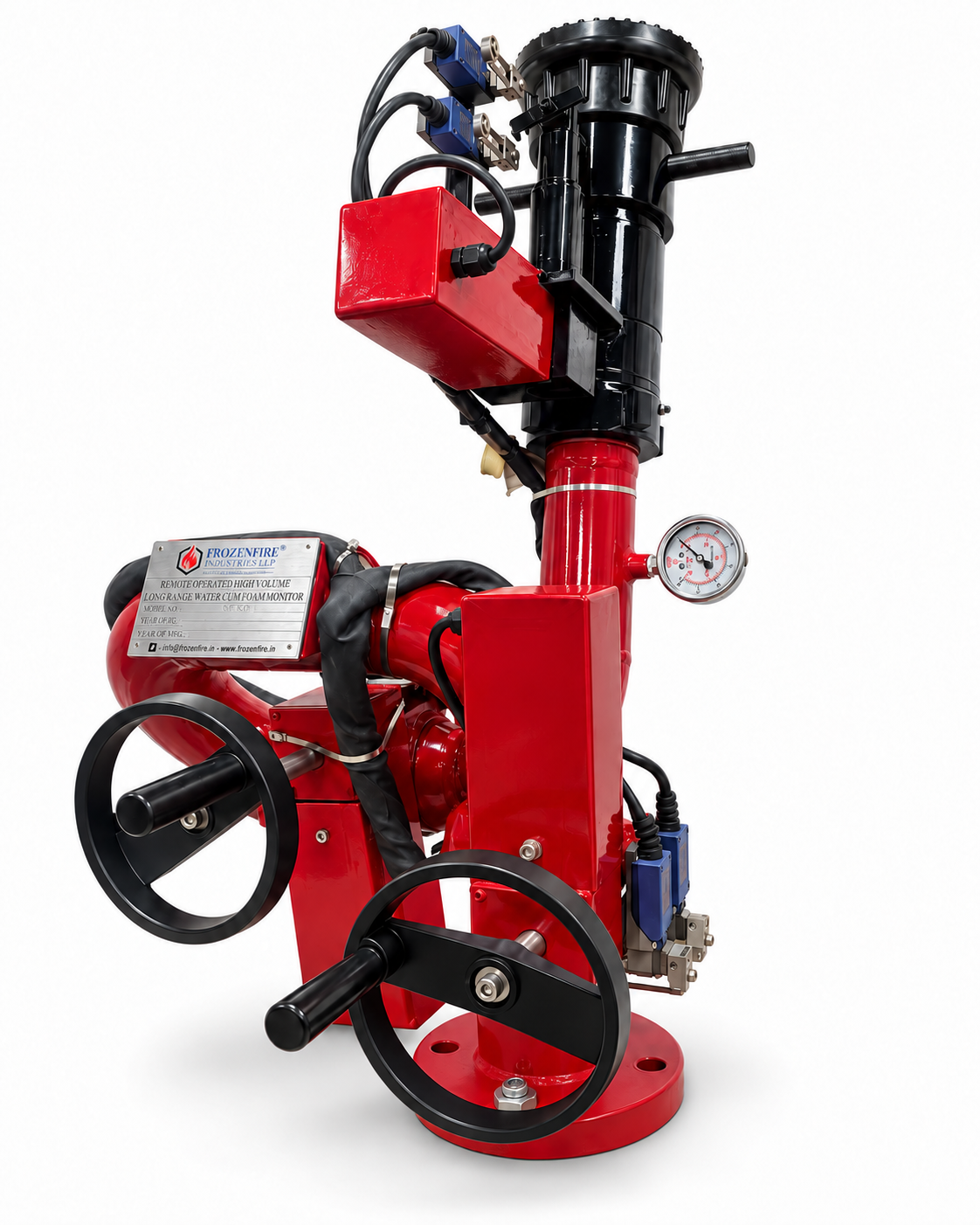
DC actuator control
Select the compatible 12V or 24V DC supply and electrical controls for the installation.

Original supplied catalogue photograph. The final model, DC supply, materials, nozzle and control package are confirmed with the approved product data.
FROZENFIRE · DC POWER · WATER & FOAM
Remote positioning. Water and foam delivery.
A DC-powered water and foam monitor with four catalogue model references from 250 to 1000 GPM, remote direction control and configurable panel, joystick or wireless operation.
These are catalogue options and ranges. Confirm the selected voltage, model duty and approved technical data before specification.
PRODUCT OVERVIEW
The Frozenfire DC remote operated HVLR monitor delivers water or compatible foam solution while allowing directional control from a remote location. DC actuators position the monitor horizontally and vertically within the selected model’s mechanical limits.
The catalogue describes compatible control-panel, joystick and wireless arrangements, with nozzle jet / spray control where configured. The supplied photograph includes manual handwheels and a pressure gauge.
Four model references cover 50, 75 and 100 mm monitor sizes. The catalogue provides selection ranges and calls for confirmation against the approved Frozenfire datasheet for the final model, electrical supply, materials and control package.
Select the compatible 12V or 24V DC supply and electrical controls for the installation.
Panel, joystick and wireless control arrangements are listed; confirm the required functions and accessories.
The pictured pressure gauge provides a reading at its measurement point. Manual adjustment follows the supplied operating procedure.
TECHNICAL SPECIFICATIONS
Pages 1–2 of the DC catalogue, revision 08/26. Review the options and confirm the selected configuration with your quotation.
Download catalogue| Parameter | Specification |
|---|---|
| Product type | DC Remote Operated Fire Water / Foam Monitor |
| Supply options | 12V / 24V DC; confirm selected voltage |
| Operation | Electrical remote control with manual handwheels as configured |
| Suitable media | Fire water / compatible foam solution |
| Catalogue flow range | 250–1000 GPM, model dependent |
| Catalogue working pressure | 7–10 bar; confirm selected duty |
| Body options | Stainless steel / mild steel |
| Geared swivel joint options | Stainless steel / gun metal |
| Nozzle material options | Aluminium / stainless steel / gun metal |
| Movement | Horizontal and vertical, within selected model limits |
| Nozzle control | Jet / spray adjustment through compatible controls, where configured |
| Electrical protection options | IP57 / IP65 weatherproof; confirm the selected enclosure |
| Control options | Monitor panel / joystick / wireless remote, as specified |
| Wireless range reference | 35 m in catalogue; confirm the selected equipment and site conditions |
| Pressure indication | Gauge shown on the supplied assembly |
| Mounting | Fixed base / flanged connection |
| Accessories | Panel-to-monitor cables and actuator MOV, if required |
The supplied catalogue asks for confirmation against an approved product datasheet. Values above describe selection options, not a single guaranteed configuration. Exact travel angles, electrical details, connection sizes and protection ratings must match the selected assembly.
MODELS & PERFORMANCE
Four model references from page 6 of the DC catalogue. Match the flow requirement, monitor size and connection to the approved duty.
Scroll sideways to see all model details.
| Monitor model | Monitor size (mm) | Flow (GPM) | Water jet (m) | Foam throw (m) |
|---|---|---|---|---|
| FIL-RO-DC-HVLR 250 | 50 | 250 | 45 | 40 |
| FIL-RO-DC-HVLR 500 | 75 | 500 | 55 | 50 |
| FIL-RO-DC-HVLR 750 | 75 | 750 | 60 | 65 |
| FIL-RO-DC-HVLR 1000 | 100 | 1000 | 65 | 60 |
Values are retained as printed, including 60 m water jet and 65 m foam throw for the 750 model. The table does not provide test conditions. Confirm discharge performance for the selected pressure, nozzle and foam arrangement.
REMOTE CONTROL CONFIGURATION
Select the DC supply and control package together. Functions, travel limits, interlocks and accessories depend on the approved configuration.
Horizontal and vertical movement using the compatible remote controls.
Jet / spray control where provided by the supplied nozzle and controls.
Control panel, joystick or wireless remote according to the specified package.
Follow the approved procedure; do not force handwheels against an energised actuator unless expressly permitted.
CONSTRUCTION & COMPONENTS
Main assembly components described in the supplied catalogue. Materials, connections and accessories depend on the selected configuration.
| Parameter | Specification |
|---|---|
| Monitor waterway | Body and barrel for water or compatible foam-solution delivery |
| DC actuators | Directional positioning through the supplied electrical control system |
| Manual handwheels | Local adjustment only as permitted by the selected configuration and operating instructions |
| Pressure gauge | Local indication at the gauge measurement point |
| Nozzle assembly | Compatible water / foam nozzle and the specified pattern-control arrangement |
| Fixed mounting | Base and flange matched to the installation and monitor duty |
OPERATION & CARE
Use the supplied operating instructions for the selected monitor, nozzle, power supply and control system.
Check mounting, supply, cables, nozzle, gauge and the movement area using the supplied operating instructions.
Operate the remote directional commands within the configured limits. Introduce the water supply gradually and monitor the operating pressure.
After foam use, flush the foam-contact parts. Follow the approved shutdown, isolation, depressurisation and inspection procedure.
Foam duty requires a compatible concentrate, proportioning system and nozzle. Trained personnel should follow the approved site procedure; isolate power and relieve pressure before maintenance.
APPLICATIONS
Application areas described in the product catalogue. Select the assembly against the project’s hydraulic, electrical and installation requirements.
INSPECTION & MAINTENANCE
The catalogue presents these intervals as a suggested starting point, not a verified model-specific maintenance schedule. Use the approved Frozenfire manual, site procedure and service conditions to set the actual intervals.
Read the maintenance guidanceDOCUMENTS & ENQUIRIES
Original seven-page catalogue, revision 08/26, with product overview, selection ranges, operating guidance, suggested maintenance, model references and troubleshooting. Final specifications require approved model data.
Original Frozenfire catalogue
Include these details in your enquiry