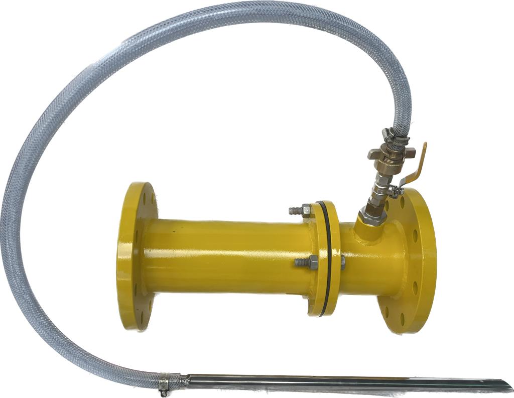
Heavy-wall stainless steel
SS 304 / SS 316 barrel and flanges form the main body of the inductor.

Flanged inductor with pickup valve, reinforced hose and stainless-steel tube. Select the flange size, connection standard, body grade and metering arrangement for your project.
FROZENFIRE · INLINE INDUCTORS
FIXED & SEMI-FIXED · FLANGED CONFIGURATIONStainless-steel construction. Flanged foam proportioning.
A heavy-wall SS 304 / SS 316 Venturi foam inductor for fixed and semi-fixed systems. Flanged connections, preset 3% or 6% induction and a complete concentrate pickup assembly support integration with foam monitors, pourers and generators.
PRODUCT OVERVIEW
The Frozenfire Flanged Inline Inductor proportions foam concentrate into a pressurised water stream through a stainless-steel Venturi nozzle and diffuser. It is designed for fixed and semi-fixed fire protection systems supplied from an external concentrate drum, tote or tank.
A heavy-wall stainless-steel barrel and flanges are available in SS 304 or SS 316. The assembly has a high-gloss safety-yellow epoxy / PU finish and flanged ends for installation in fire-water headers, foam pump rooms and mobile skid platforms.
The pickup kit includes a stainless-steel isolation ball valve, quick-connect fitting, clear reinforced suction hose and a rigid stainless-steel pickup tube. A non-return check valve controls backflow toward the concentrate supply.
SS 304 / SS 316 barrel and flanges form the main body of the inductor.
A stainless-steel convergent nozzle produces suction; the divergent section mixes concentrate with the water stream.
Choose 3% or 6% induction. Custom metering is available for the specified duty.
An SS isolation ball valve, quick-connect fitting, clear reinforced hose and angled-tip SS pickup tube connect to the external concentrate supply.
A built-in brass / stainless-steel check valve is provided to prevent water backflow into the concentrate drum or tank.
ANSI B16.5 Class 150 / BS 4504 PN16 Table RF connection options support rigid inline installation.
TECHNICAL DATA
Construction, connections and pressure data from the Flanged Inline Inductor catalogue, revision 07/26.
Download PDF| Parameter | Catalogue information |
|---|---|
| Product type | Flanged inline Venturi foam inductor |
| Body material | SS 304 / SS 316 heavy-wall barrel and flanges |
| Inlet & outlet connections | Flanged ANSI B16.5 Class 150 / BS 4504 PN16 Table RF |
| Available flange sizes | 3″ (80 NB), 4″ (100 NB), 6″ (150 NB) |
| Proportioning ratio | 3% or 6% preset induction; custom metering available |
| Foam pickup assembly | Clear reinforced PVC hose, SS pickup tube, SS ball valve and check valve |
| Working pressure range | 7–12 bar |
| Hydrostatic test pressure | 21 bar |
| External finish | Anti-corrosive high-gloss safety-yellow epoxy / PU coating |
Select the flange standard, size, stainless-steel grade and metering arrangement to match the installation. The 21 bar hydrostatic value is a test pressure; the specified working range is 7–12 bar.
Catalogue flow ranges for each size. Select the inductor’s rated duty to match the downstream foam equipment.
| Flange size | Nominal bore | Flow capacity |
|---|---|---|
| 3″ | 80 NB | 600–1200 LPM |
| 4″ | 100 NB | 1200–2200 LPM |
| 6″ | 150 NB | 2200–3500 LPM |
WORKING PRINCIPLE
Venturi induction uses the water supply to draw concentrate into the flowing stream.
Water enters through the inlet flange and passes through the stainless-steel convergent nozzle, creating a low-pressure suction zone.
Atmospheric pressure drives concentrate through the stainless-steel pickup tube, reinforced hose and open isolation valve into the suction chamber.
Concentrate mixes with the water in the divergent diffuser. The foam solution flows to the connected foam monitor, pourer or generator.
OPERATION
Product catalogue guidance to use with the selected equipment and the facility’s operating procedure.
Check that flange bolts are evenly tightened with the correct gaskets installed. Match the body’s flow-direction arrow to the pipeline flow.
Insert the stainless-steel pickup tube to the bottom of the concentrate drum, tote or tank. Open the foam isolation ball valve before starting water flow.
Open the main water isolation valve gradually to achieve the required duty within the 7–12 bar working range. Check the clear suction hose for continuous concentrate flow without trapped air.
After use, close the main water supply and move the pickup tube into a container of clean fresh water.
Re-pressurise the water line and flush for 2–3 minutes, continuing until clear water is drawn through the pickup hose and discharged.
Close the foam ball valve, disconnect the pickup hose, drain residual water and secure the system.
APPLICATIONS
Applications and installation settings described in this product’s catalogue. Select the equipment and concentrate arrangement for the protected hazard.
INSPECTION & MAINTENANCE
After-use care, monthly inspection and annual maintenance from the product catalogue. Include these in the equipment’s maintenance programme.
TROUBLESHOOTING
Checks from the Flanged Inline Inductor catalogue. Isolate, depressurise and drain the line before opening the inductor or servicing its check valve.
DOCUMENTS & SUPPORT
Download this product’s original PDF or discuss the selected configuration with Frozenfire.
Original product literature
Flange configurations, size-wise flow ranges, pickup assembly, operating instructions, maintenance and troubleshooting.
Download PDF Open catalogueProduct and project enquiries
Share flange size and connection standard, required flow and inlet pressure, SS grade, concentrate type, proportion, installation drawing and quantity.
Request technical detailsEXPLORE THE RANGE
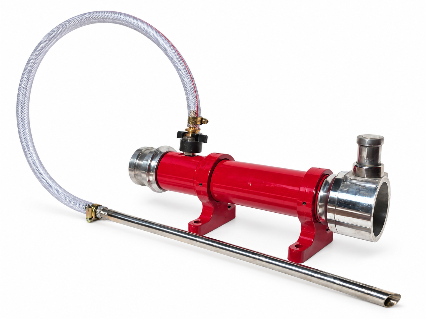
A portable Venturi inductor that draws foam concentrate from an external container into the water stream at a preset proportion. Instantaneous male inlet and female outlet connections support quick integration with compatible foam delivery equipment.
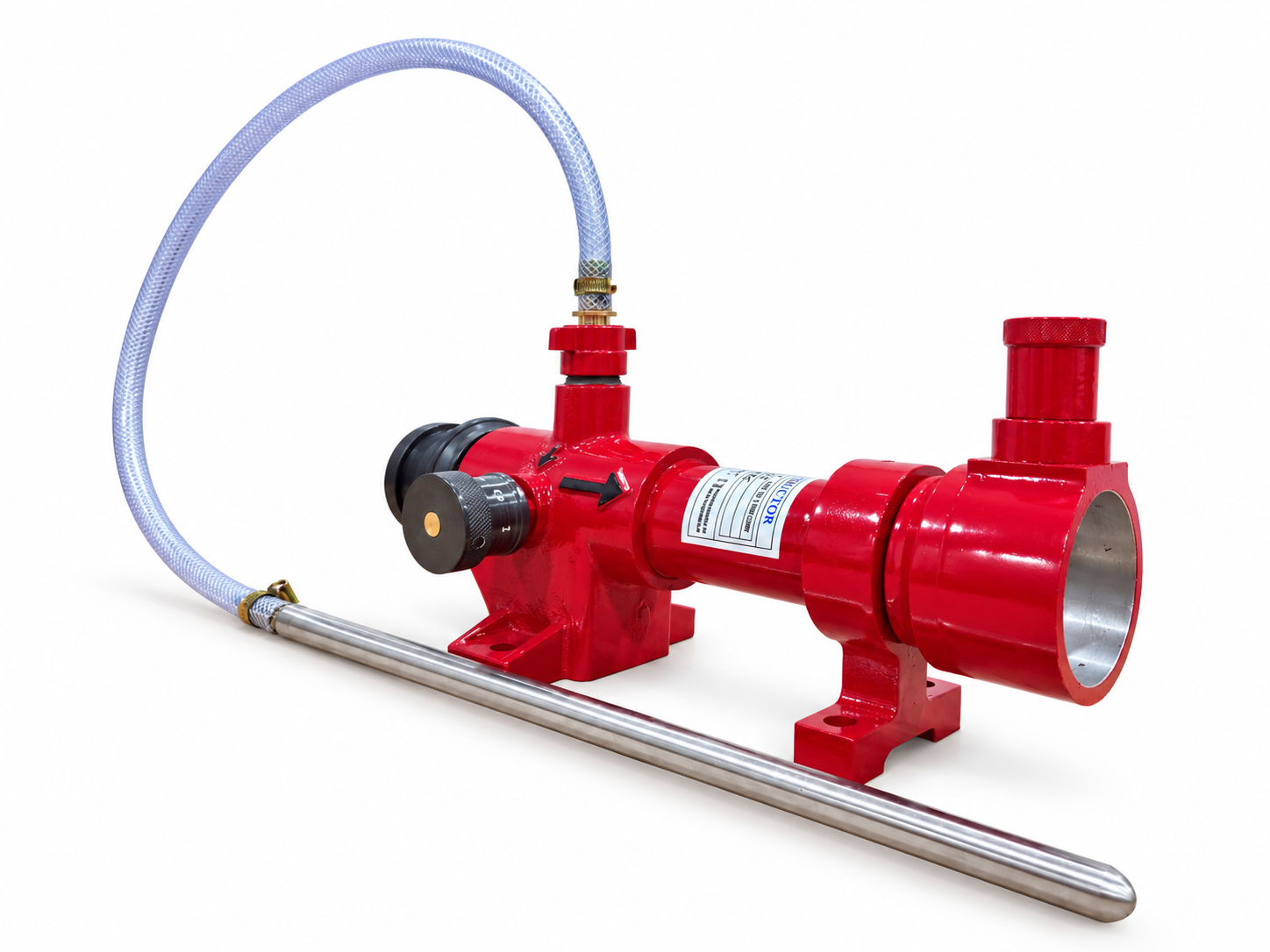
An aluminium inline foam inductor with selectable 0%, 1%, 3% and 6% foam-proportion settings. Venturi-based operation draws concentrate through the pickup hose for compatible mobile and fixed foam-system arrangements.