Two independent outlets
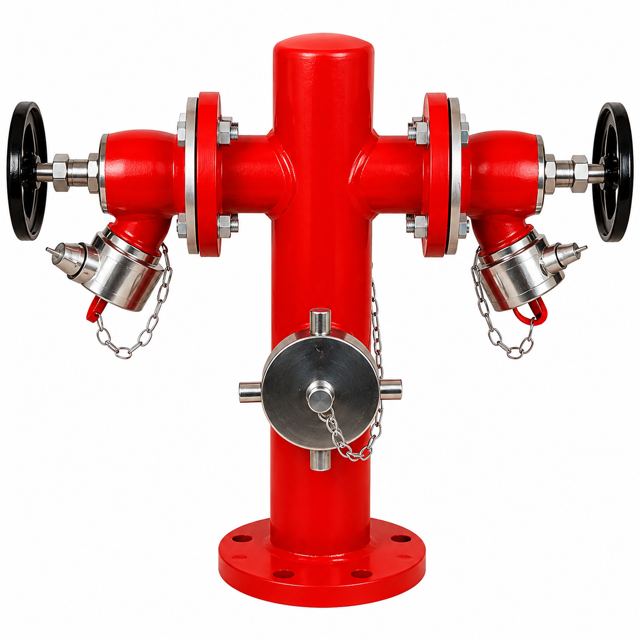
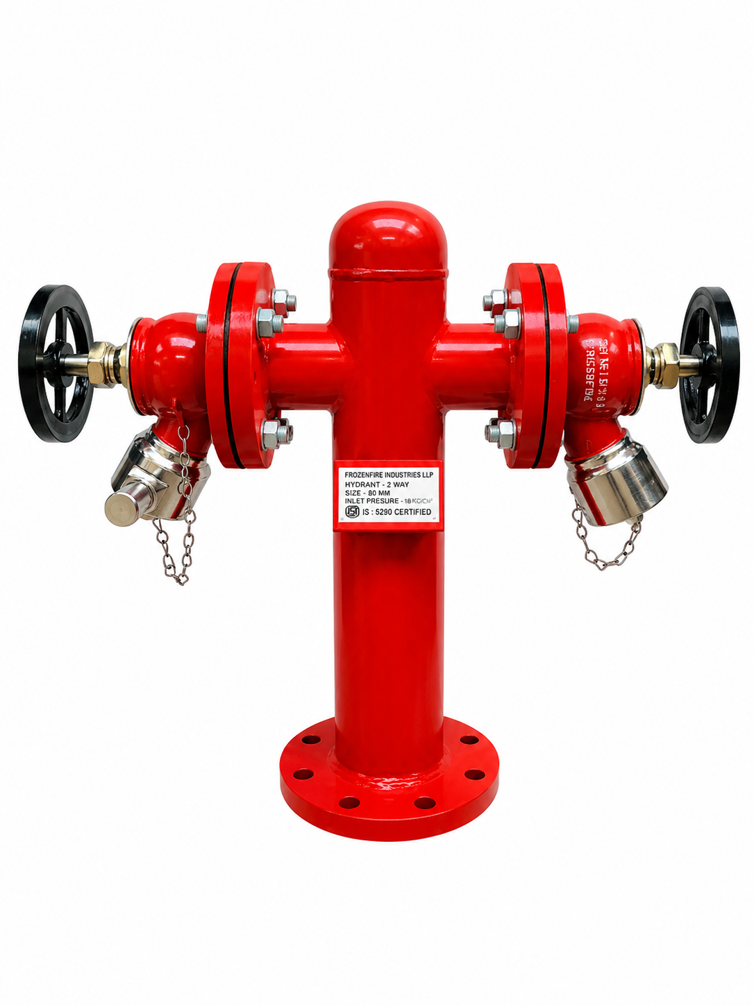
Two 63 mm (2½″) instantaneous hose outlets with separate shut-off valves.

Catalogue configuration shown. Material, connections, height and accessories are confirmed with your quotation.
FROZENFIRE · FIXED STAND POST
Two outlets. Independent valve control.
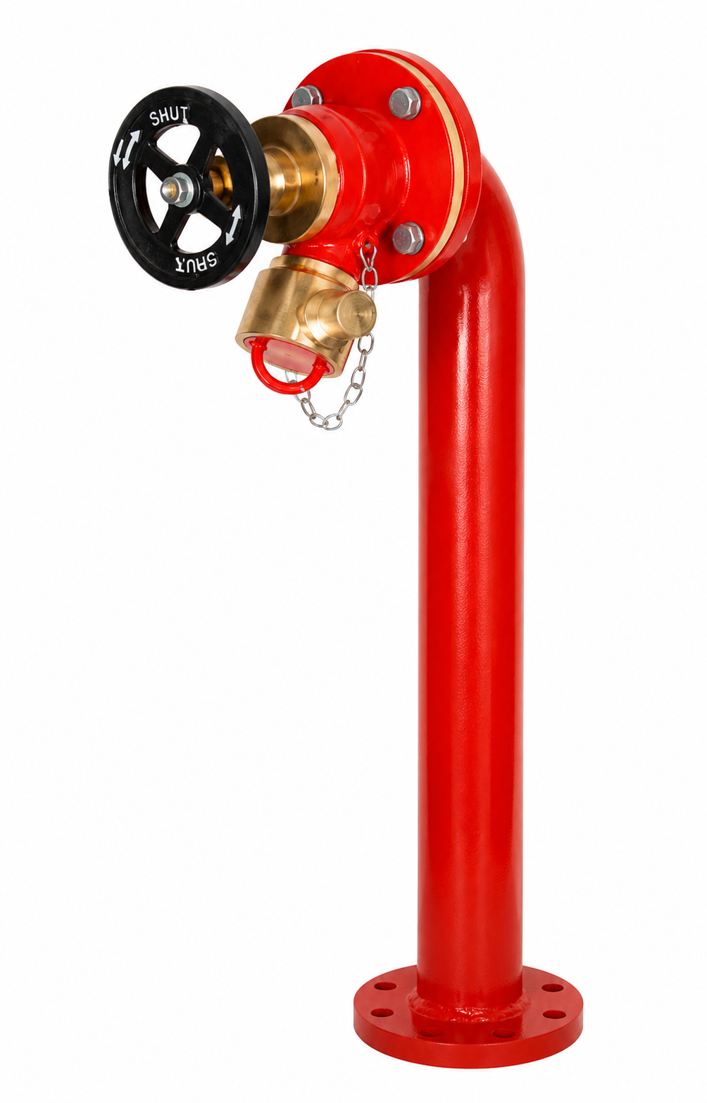
A fixed fire hydrant stand post with two 63 mm instantaneous hose outlets, each controlled by its own shut-off valve.
PRODUCT OVERVIEW
The Double Headed Stand Post brings two hose connections together on a single fixed hydrant body. Each outlet has independent valve control, allowing hose lines to be selected and regulated for the response arrangement.
The catalogue specifies carbon-steel or stainless-steel construction, replaceable valve seats and stainless-steel or gun-metal spindles. Two-line operation depends on the available water supply and pressure of the fire-water system.
Two 63 mm (2½″) instantaneous hose outlets with separate shut-off valves.
Replaceable valve seats and stainless-steel or gun-metal spindles.
Epoxy coating and weatherproof blank caps with retaining chains.
TECHNICAL SPECIFICATIONS
Model features and typical range data from the Fire Hydrant Stand Post catalogue.
Two hose outlets with compatible instantaneous hose connections.
| Parameter | Specification |
|---|---|
| Product family | Fire hydrant stand post |
| Body material | Carbon steel / stainless steel, as selected |
| Hydrant valve material | Stainless steel / gun metal, as selected |
| Hose outlets | 2 × 63 mm (2½″) instantaneous |
| Inlet connection | Flanged; ANSI / IS drilling as selected |
| Stand post height | 600 mm typical; customised height available |
| Working pressure | Up to 16 bar — typical range value* |
| Hydrostatic test pressure | Up to 24 bar — typical range value* |
| Operation | Manual handwheel |
| Flow direction | Straight through |
| Finish | Fire-red epoxy powder coating / epoxy finish as applicable |
| Installation | Fixed, vertical, above ground |
| Temperature range | −10°C to +80°C — typical range value* |
| Outlet protection | Blank caps with retaining chains |
| Valve control | Independent shut-off valve for each hose outlet |
| Spindle material | Stainless steel / gun metal, as selected |
* These are typical stand-post range specifications. Confirm the final material, height, connections, working pressure, test pressure and temperature limits against the selected configuration. Hydrostatic test pressure is not the operating pressure.
CONFIGURATION & SELECTION
Discuss these range options with your enquiry. The final assembly and supplied accessories follow the agreed configuration.
Share the outlet arrangement, body and valve materials, inlet flange details, required height, operating pressure, quantity and delivery location. Include the installation drawing where available.
OPERATION
Catalogue guidance for trained personnel following the applicable hydrant-system procedures.
Check the stand post, valves and accessible connections before use. Ensure the operating area and hose route are clear.
Remove the outlet cap and securely connect a compatible hose. Check the coupling engagement and hose arrangement.
Operate the handwheel gradually in the indicated opening direction and regulate the water supply for the required duty.
Close gradually after use. Confirm that residual pressure has been relieved before disconnecting, replace caps and check for leakage.
Avoid sudden valve operation. Secure hose connections before establishing flow and confirm that residual pressure has been relieved before disconnection.
APPLICATIONS
Application areas listed in the product catalogue. Equipment selection remains subject to the site’s hydrant layout and duty.
INSPECTION & MAINTENANCE
Follow the catalogue schedule together with the site’s maintenance programme. Isolate and depressurise before servicing; never dismantle a pressurised hydrant.
| Activity | Frequency |
|---|---|
| Visual inspection | Monthly |
| Operational check | Quarterly |
| Flushing & cleaning | Every 6 months |
| Lubrication | Every 6 months or as required |
| Pressure & flow test | Annually |
| Complete overhaul | Every 3–5 years or as required |
DOCUMENTS & SUPPORT
Keep the original catalogue to hand, print this page or request information for your selected configuration.
Original Frozenfire catalogue
Single headed, double headed and pumper-connection stand posts. Features, typical specifications, operation and maintenance.
Download catalogue Open PDFProduct and project enquiries
Share the outlet arrangement, body and valve materials, inlet flange details, required height, operating pressure, quantity and delivery location. Include the installation drawing where available.
Request technical detailsEXPLORE THE FAMILY